A diode effectively serves as a one-way switch for electrical current, enabling it to easily flow in one particular direction while restricting its ability to flow in the opposing direction.
Diodes are rated depending on their current capacity as well as their type and voltage and have a polarity that is determined by a positive and negative lead, known as an anode and cathode.
The great majority of diodes only allow current to flow when the anode receives positive voltage. A diode that allows current flow is known as forward-biased, with reverse-biased the name given to a diode that is not permitting the flow of current.
Diodes are tested with digital multimeters in order to make sure that the forward and reverse bias modes are in proper working order.
Testing Diodes With A Digital Multimeter
There are two methods by which a diode can be tested with the use of a digital multimeter. The best approach is usually the Diode Test mode, but Resistance mode can be made use of in the event that a multimeter does not actually have the former.
If Resistance mode is being used to test a diode, it is important to keep in mind that this does not always indicate as to whether or not the diode is actually good or bad.
The test should not be carried out in this mode if the diode is connected within a circuit as this can result in a false reading. However, Resistance mode can be used to verify if a diode is good or bad within specific applications after this has been indicated by a Diode Test.
The best way to test a diode is to measure the voltage drop across it when forward-biased, as this acts as a closed switch and enables the flow of current.
The Diode Test mode on a digital multimeter creates a small voltage between the test leads and then displays the drop in voltage after those leads have been connected across a forward-biased diode.
Test Procedure
The first step in testing a diode with a digital multimeter is to ensure that all power going to the circuit has been turned off and that there is no voltage at all in the diode. Charged capacitors can sometimes mean there is the voltage in the circuit, in which case they will have to be discharged.
The multimeter should be set to measure either dc or ac voltage as necessary.
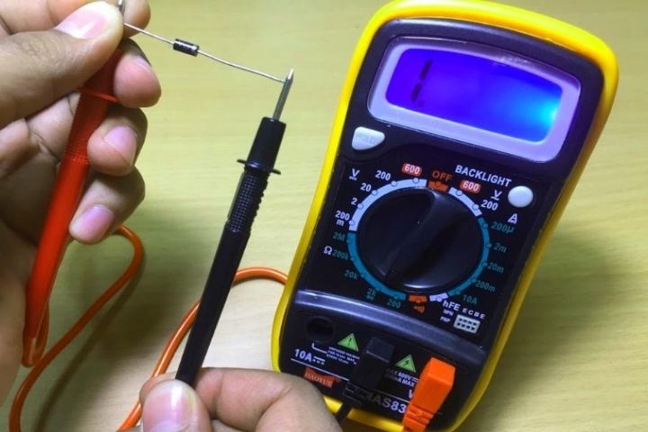
The rotary switch dial should be turned to Diode Test mode, and the test leads connected to the diode, with the displayed measurement recorded. The test leads should then be reversed and the displayed measurement again recorded.
Analysis
A voltage drop that ranges from 0.5 – 0.8 volts for most silicon diodes will be displayed by a good forward-biased diode. When reverse-biased a good diode should result in an OL display on the digital multimeter, which indicates it is functional as an open switch.
A bad diode will not allow current to flow in any direction, and OL will display on the multimeter in both directions. The same voltage drop reading – around 0.4 volts – will result in both directions from a shorted diode.
Testing a diode is the only way to make certain it is working in the correct manner.


![TamilRockers Proxy 11 Mirror-Sites [Updated 2022] & How to Unblock It](https://www.techsplashers.com/wp-content/uploads/2022/01/TamilRockers-Proxy-11-Mirror-Sites-Updated-2022-How-to-Unblock-It.jpg)

Leave a Reply